
 Tiếng Việt
Outline
There are two proven methods to ensure actuator operation during a power outage:
-
Using a DC motor
-
Using an air motor
Historically, DC motor-type actuators have been widely used for emergency isolation valves in power plants, as well as in water supply and sewerage systems.
Requirements for DC Motors
-
High starting torque characteristics suitable for valve operation.
-
Line-start applicable motors:
– Unlike general-purpose DC motors, these do not require current-limiting resistance at startup or a complex switching circuit.
– This simplifies the overall circuit design.
Specifications of DC Motor
-
Excitation type: Self-excitation / cumulative compound type.
-
Power supply options:
– 100 V, 110 V, 115 V
– 200 V, 230 V, 250 V (optional) -
Size (output based on starting torque):
#2, #5, #7.5, #10, #15, #25, #40, #60, #80, #100, #150, #200 -
Operating time (Short-time rating):
– 20% load (Intermediate load)
• #2 to #25: 15 mins
• #40 to #200: 5 mins
– 40% load (Intermediate load)
• #2 to #25: 7.5 mins
• #40 to #200: 2 mins -
Brake (Optional)
DC motor connection diagram
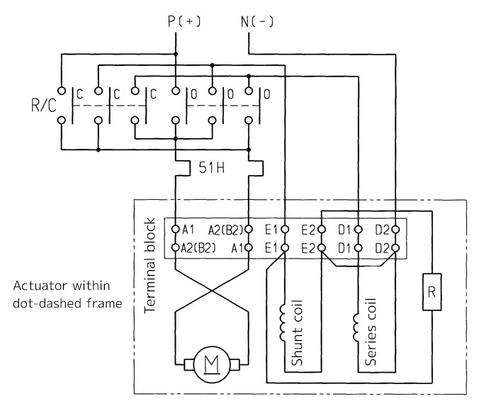
Notes (Connection Diagram & Symbols)
– R/C: Reversible electromagnetic switch
– 51H: Thermal relay heater
– R: Discharge resistance
Important:
-
External wiring to E2 terminal is prohibited.
-
“R” indicates discharge resistance.
-
For motor size #7.5 and above (with interpole), B2 is used instead of A2 as the terminal marking.


Reviews
There are no reviews yet.